FAQ/009 KAM-500 - KAD/ADC/109/S2: I’m using the KAD/ADC/109/B/S2 module. If I do not want to use the sense line, what do you recommend?
Connect the sense line + to the excitation + (respectively sense line - to the excitation -) with a short or tick cable. Sense lines are for compensating voltage drop over excitation lines (cable resistance). Those drops causes gain error of measurement. But with short or/and thick cables, this should be negligible.
FAQ/010 KAM-500 - KAD/ARI/001: What steps should be taken if the KAD/ARI/001 is not receiving expected messages?
If not receiving an expected ARINC-429 message with a KAD/ARI/001, check the following list of common errors:
- Ensure that the +/- Bus is not inverted in the wiring
- Ensure that the right bus is connected to the KAD/ARI/001
- Ensure the Bus speed is correct
- Check the ‘Error Bits’ from the REPORT parameter: If there is an error, the card will not display WD_COUNT or the Label.
- The ARINC labels are often expressed by the avionics documentation in octal. The KSM-500 software allows these to be configured as decimal, octal, or hexadecimal.
Please ensure that the correct label is entered into the software.
FAQ/011 KAM-500: Is it possible to replace the Compact Flash card in a KAD/MEM/004 Module?
Yes. Curtiss-Wright recommends sending the module under RMA to replace the CompactFlash card.
The CompactFlash card can also be replaced on-site under some special conditions and considering the following:
- Curtiss-Wright runs Production and ATP tests on the KAD/MEM/004 before shipment, therefore if the CompactFlash card is replaced on-site Curtiss-Wright can't guarantee that it will work (even if the manufacturer of the CompactFlash card is the same).
- Same capacity CompactFlash: It's possible to change the CompactFlash in the KAD/MEM/004 for a CompactFlash of the same capacity.
- Different capacity CompactFlash: It's possible to change the CompactFlash for a CompactFlash of different capacity but it also requires also a change of the module type. The capacity of the CompactFlash must match the capacity of one of the KAD/MEM/004 supported by KSM-500 Software.
FAQ/008 GTS-500: I’m having issues to get the lock with the GTS/DEC/00x when I’m using video parameters from the KAD/VID/103 in a PCM frame with PCM code NRZ-L. How I can resolve this?
Obtaining a lock using NRZ-L in this case will not be easy. RNRZ-L is recommended for data that contains long sequences of 0’s or 1's which is often the case with video data. NRZ-L can be used effectively with regular data with enough transitions or if the video data is interleaved with fill data.
FAQ/013 KAM-500: Could you give us more information on the Audio format used by the KAD/VID/103?
The KAD/VID/103 uses the IMA ADPCM codec in a private transport stream of the MPEG-2 transport stream generated by the KAD/VID/103. Transport stream constants used in the VID/103
- AUDIO PID is 1001
- VIDEO PID is 1000
- Length of the audio PES packets is 0x20E
- Length of the audio PES header is 0x10
PES constants
- MINPESHDRLGT is (9)
- PESPTSOFFSET is (9)
- PESHDRPTSLGT is (14)
IMA ADPCM algorithm
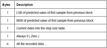
The first thing to note about this process is that Microsoft's implementation uses two distinct packet formats, one for mono and one for stereo. You need to know which type of packet you're attempting to decode before you start the decoding process. Normally this would be easy enough when processing something like a .wav file - you'd just read the header for the relevant information. For a Mono packet we get the following details
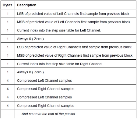
The Stereo packet is very similar, except has two channels instead of one and interleaves the encoded data.
Defines for the IMA ADPCM algorithm
- #define AUDIOPACKETSIZE (1025)
- #define AUDIOPACKETADJMAX ((AUDIOPACKETSIZE)/16)
- #define AUDIOPACKETMS (64) // no. of milliseconds between audio packets
- #define AUDIOPACKETTIME (5760) // no. of PTS ticks between normal audio pkts
- #define SKIPPACKETS (5)
- #define LARGEOUTOFSYNCH (SKIPPACKETS*AUDIOPACKETTIME)
- #define MILLISECONDSYNCH (AUDIOPACKETTIME / AUDIOPACKETMS)
static ADPCMCOEFSET MSADPCM_CoeffSet[numCoef] = { {256, 0},{512, -256}, {0, 0}, {192, 64}, {240, 0}, {460, -208}, {392, -232} };
// pertinent tables for IMA ADPCM
static int adpcm_step[89] =
{
7, 8, 9, 10, 11, 12, 13, 14, 16, 17,
19, 21, 23, 25, 28, 31, 34, 37, 41, 45,
50, 55, 60, 66, 73, 80, 88, 97, 107, 118,
130, 143, 157, 173, 190, 209, 230, 253, 279, 307,
21 Feb. 2011 | FAQ/071
337, 371, 408, 449, 494, 544, 598, 658, 724, 796,
876, 963, 1060, 1166, 1282, 1411, 1552, 1707, 1878, 2066,
2272, 2499, 2749, 3024, 3327, 3660, 4026, 4428, 4871, 5358,
5894, 6484, 7132, 7845, 8630, 9493, 10442, 11487, 12635, 13899,
15289, 16818, 18500, 20350, 22385, 24623, 27086, 29794, 32767
};
static int adpcm_index[16] =
{
-1, -1, -1, -1, 2, 4, 6, 8,
-1, -1, -1, -1, 2, 4, 6, 8
};
FAQ/014 KAM-500 - SAM/DEC/007: What are the steps to install the SAM/DEC/007/C under Windows 7 32 bits?
1. Set your windows privileges to administrator
2. User Account Control: Set 'User Account Control settings' to Never Notify me:
- Start -> Control Panel -> System and Security
- Under 'Action Centre', change User Account Control Settings
- Never Notify: Choose this only if you need to use programs that are not certified Windows 7 because they do not support User Account Control.
3. Driver Signature Enforcement: On Windows boot, press F8 - Select option 'Disable Driver Signature Enforcement'.
4. The same device driver is used for Windows 2000, XP, Vista and Windows 7. However, for Windows 7, go to control panel, start Device Manager by selecting start and then begin typing 'Device Manager' in the window.
5. Device Manager opens in a list. Select it and press Enter. Click on 'PCMCIA adapters'.
6. Right-click on the first adapter in the list and select 'Update driver software'.
7. Select 'Browse my computer for driver software' and navigate to the following location on the driver CD '\DRIVERS\WIN_2K_XP'. Click 'Ok' then click 'Next' to install the driver.
If errors still occur, contact Acra support detailing the errors encountered.
FAQ/015 KAM-500: Can a differential input analog module be used by a single ended transducer?
Yes. A single ended transducer can be can be captured by a differential input by connecting the negative input of each channel to GND.
Make sure that the sensor has the same GND reference. A resistor (10K or 20K) can be used between the sensor reference and the KAM-500 GND if required.
FAQ/016 KAM-500: Can I have two different PCM stream coming out of the KAM-500 system?
It is possible to have two different PCM streams coming out from a KAD/BCU/101 and a KAD/ENC/106 for example. These can have different bit rate, frame placement and so forth. The only rule to consider is that the acquisition cycle has to be the same all along the system.
For example:

FAQ/017 KAM-500: Can I swap two modules with the same part number in the chassis without reprogramming the system?
Yes, but only if the two modules had previously been programmed with the same settings.
FAQ/018 KAM-500: Can I upgrade a KAM module to a KAD module?
This operation can be done under the RMA process only. Please contact Curtiss-Wright at [email protected] for more information.
FAQ/019 KAM-500: How are the connector and module pinout numbered for a KAD connector?
Mating face of the module’s KAD connector (male)
Mating face of the KAD mating connector (female)
FAQ/020 KAM-500: How close can KAM-500 chassis be to each other?
Each chassis is required to operate with a chassis temperature between –40C and +85C, so the location may vary from one application to another.
Depending on the loading, the type of chassis and its environment, two chassis can be set side-by-side.
To know how much heat your chassis is dissipating, please refer to TEC/NOT/016.
FAQ/021 KAM-500: In which order should I set up my modules in a chassis?
The controller module such as the KAD/BCU/101 or KAD/BCU/105 must be placed in slot J2. Any other module type can be set at any slot of chassis – except for 2 user-slot modules such as KAD/VID/103 which cannot be set in slot J3 as J2 is reserved for the controller module.
One thing that should be considered is how much power is used by a system and if the chassis can handle this amount of power. To check this, please refer to the application notes handbook or download TEC/NOT/016.
FAQ/022 KAM-500: What are the main improvements of the Series 100 family of analog modules?
The main improvements are:
- Higher accuracy – Typically 0.08% FSR at analog gains of 100
- Higher bandwidth – Typically 6KHz
- Higher access rate – Typically 2M Samples per second
- Faster programming – Typically 5 seconds per analog module
- Smaller digital filter delay - (8 order Butterworth filter versus Kaiser FIR – see data sheets for details)
- 16 bits ADC
Curtiss-Wright recommends 100 family modules for new programs.
FAQ/023 KAM-500: What is the difference between DNC (Do not connect) and NC (Not connected) as a pin description in KAM-500 data sheets?
NC means the pin is not connected to the module.
DNC is used for two reasons:
- The pins are reserved and may be used in a later revision.
- The pins could be undocumented inputs or outputs for internal test purposes or reserved for a customer-specific requirement.
It is important to follow the instruction and not connect the pin.
FAQ/024 KAM-500: What is the real sampling frequency of a parameter that goes to different destinations at different rates? What is the real cut-off frequency of the filter?
To know the real sampling frequency of a parameter when there is more than one "Sink" in the system (PCMs, Ethernets or CompactFlash Memory module), all the "Sinks" where this parameter is going to have to be considered. The real sampling frequency will be the highest i.e. if the same parameter mentioned above is sent at 50 Hz in the PCM Frame is logged into a CompactFlash Memory at 400 Hz, the real sampling frequency for the parameter will be 400 Hz.
In the last example, if a parameter coming from an Analog Module has the cutoff frequency set to Fs/4, the real cut-off frequency of the filter will be 400/4=100 Hz (as opposed to the 12.5 Hz that you’d expect if looking only at the PCM Sampling Rate). 23
FAQ/025 KAM-500: What voltage I am measuring with my quarter-bridge?
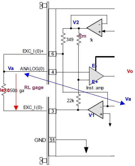
Vo = E+ – E
Voltage at E-:
The voltage Va is a virtual ground so E- = 0V
Voltage at E-:
E+ = (V2+V1)/2
With V2=Iexc x Rm and Vl=-Iexc x RL
So: E+ = Iexc x (Rm-RL)/2
Vo = Iexc x (Rm-RL)/2 – 0

FAQ/026 KAM-500: What will happen if the chassis temperature is higher than 85 degrees or lower than -40 degrees?
The main effect is modules could have a greater error than specified. For example, an analog module’s accuracy will be reduced and bus monitors will produce higher data error rates. In general, the modules might fail partially or completely.
The second effect is a thermal stress which will age the components and integrated circuits, reducing the mean time to failure.
FAQ/027 KAM-500: Why does Curtiss-Wright specify "Chassis" and not "Ambient" temperature on the datasheet?
The reason Curtiss-Wright specifies "Chassis" and not "Ambient" temperature is because
- The customer is responsible for knowing the power consumption and ensuring there is adequate heat dissipation from the KAM-500 in its installation by means of a thick metal mounting plate or heatsinks. Specifying Chassis temp makes this point clear to the customer. Otherwise customers may, for example, mount the unit to a thin metal or composite structure inside an insulated compartment.
- Ambient is not clearly defined. There is little point in specifying a module will work at "Ambient" i.e. at sea level with circulating air, 50% RH and in a temperature chamber with 15cm spacing to the walls of the chamber. In reality the unit will have to function at a very different Ambient i.e. 50,000 ft with no circulating air, 20% RH, and another hot system placed 2 cm away from it. Never the less, all KAM-500 modules are tested as part of Design Verification in a chassis in a temperature chamber, and the "ambient" temperature of the circulating air is varied from -40 C to +85 C.
FAQ/028 KAM-500: Why is the checksum of the UDP packet from the KAD/ETH/101 and KAD/BCU/105/B modules always 0x0000?
The KAD/ETH/101 and KAD/BCU/105/B modules are compliant with the UDP-IPv4 standard. The checksum is optional – the value 0x0000 means that the checksum is not used.
FAQ/029 KAM-500: Why is the green LED on my chassis blinking?
This is a sign that there is a malfunction in the system (not necessary in that chassis).
Some steps for investigating the problem are as follows:
- Remove all the modules from the chassis and check the power lead and that 28V does not flick. The chassis can operate with an input voltage varying from +18V up to 40V. If the LED flickers without any modules in it and the 28V is stable then the chassis should be returned to Curtiss-Wright through the RMA process by sending a mail to [email protected]
- If the above is good, then replace the modules back into the chassis one at a time starting with the controller module such as the KAD/BCU/101 or KAD/BCU/105. Power up the chassis as each module is added to confirm if the LED is blinking. If the LED flickers after one of the modules is placed into the chassis then this module is faulty and should be returned to Curtiss-Wright through the RMA process at the address given above.
- If all the modules and chassis are good then the connectors on each module should be connected one by one until the faulty connection is found – in this instance, the cabling will need to be verified.
FAQ/080 KAM-500 - How do I connect a 4 wire 100Mbps Ethernet cable to the KAD/EBM/102?
You can connect an Ethernet cable to the KAD/EBM/102 using pinout diagrams – the KAM-500 pinout details can typically be found in the data sheet. The following table outlines what connections should be made:
| Ethernet Cable | 1000BaseT Signal | KAD/EBM/102 Pin |
|---|---|---|
| Transmit+ | BI_DA+ | 33 |
| Transmit- | BI_DA- | 32 |
| Receive+ | BI_DB+ | 31 |
| Recieve- | BI_DB- | 30 |
| Unused | BI_DC+ | 29 |
| Unused | BI_DC- | 28 |
| Unused | BI_DD+ | 35 |
| Unused | BI_DD- | 34 |
FAQ/081 KAM-500 - Why can I not establish a reliable connection with an Ethernet switch?
Say you have a system with an Acra KAM-500 with a KAD/BCU/140 controller and a NET/SWI/003 for example and you are receiving the error message 'Could not establish or maintain reliable connection'. You have set the NET/SWI/003 ports to 100Mbps band can both of the devices. The likely reason for such an issue is the PC auto-negotiation.
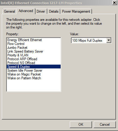
In Windows 7 Control Panel, go to 'Change Adapter Settings' under 'Network and Sharing Center' and select the 'Ethernet NIC' connected to the NET/SWI/003.
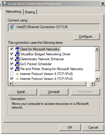
Select 'Configure', then the 'Advanced' tab and select 'Speed & Duplex' and set the value to '100Mbps Full Duplex'.
