- Overview
- Specifications
- Downloads
- Featured Products
- Request a Quote
- Product Support
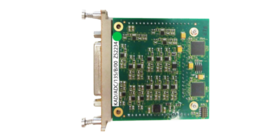
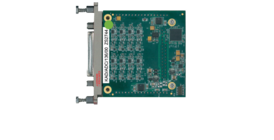
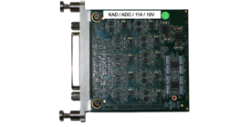
The KAD/ADC/114 is used to condition and digitize up to 16 differential-ended analog channels. At the heart of the KAD/ADC/114 is a hard-wired state machine that oversamples all channels at a rate between 48 ksps and 96 ksps and digitally filters any noise above the user-programmable cutoff frequency.
This is achieved using cascaded, half-band, Finite-Impulse-Response (FIR) filters followed by an 8th order Butterworth Infinite-Impulse-Response (IIR) filter with a default cutoff point set at one-quarter of the sampling frequency (fc = fs / 4). All signals are sampled simultaneously. Thus, when several channels are sampled at different sampling rates, at the start of an acquisition cycle all channels are aligned.
Excitation on the KAD/ADC/114 is programmable using four D/A converters, each of which is connected to two pairs of drivers. If more than eight excitations are required, each excitation output can be connected to two bridges.
The KAD/ADC/114 is available with three different input ranges (±10V, ±1V, and ±100mV). The input range must be specified when ordering.
Features
- 16 full or ½bridge, potentiometer or differential ended input channels
- Ordering input range (±100mV, ±1V,±10V)
- High accuracy (0.01% FSR typical for /1V, /10V variant, 0.02% FSR for /100mV variant)
- Programmable voltage excitation per two channels and balance adjust per channel
- Shorts only affect channels sharing excitation
- 16-bit simultaneous sampling on each channel
- Up to 12 k samples per second per channel
- Up to 3 kHz Bandwidth (AAAF filter)
Applications
- Analog signal Acquisition Differential Ended
- Full Bridge
- Half Bridge
- Potentiometer
Data Sheet
User Manual
Brochure
KAD/ADC/114


